Airpot Precision Dashpots in custom configurations which offer a range of sizes and capabilities likely to satisfy many requirements in which accurate and repeatable control of force and or impact is desired. Custom Airpot Dashpots have been catagorized in 6 bore diameters ranging from .22 inches to 1.75 inches with either push, pull, or two-way damping. Within specified limits you can obtain a specific stroke, mounting length, rod type and rod end design. Additional custom configurations are possible with Airpot engineering collaboration.
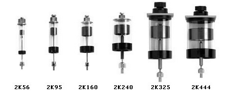
| MODEL | 2K56 - Bore Size: .220" (5.59 mm) |
2K95 - Bore Size: .366" (9.3 mm) |
2K160 - Bore Size: .627" (15.93 mm) | 2K240 - Bore Size: .945" (24 mm) | 2K325 - Bore Size: 1.281" (32.5 mm) | 2K444 - Bore Size: 1.750" (44.4 mm) |
| BORE (inches) | 0.22 | 0.366 | 0.627 | 0.945 | 1.281 | 1.75 |
| STROKE RANGE (inches) (any x.xxx) | .125 - 11.0 | .125 - 11.0 | .125 - 13.0 | .125 - 12.0 | .125 - 10.0 | .125 - 8.0 |
| FIXED STROKE FOR SNUBBER MODELS (inches) | N/A | N/A | 1.5 | 2 | 2 | 2 |
| FORCE CAPACITY: PULL DAMPING DIRECTION lbs force (Starting from fully retracted position) | 0.5 | 1.4 | 4 | 9 | 17 | 30 |
| FORCE CAPACITY: PUSH DAMPING DIRECTION lbs force (Starting from fully extended position) | 0.35 | 1 | 3 | 7 | 13 | 24 |
| APPROX. ENERGY CAPACITY: PULL DAMPING DIRECTION FOR 1 IN. STROKE (inch-lbs) | 0.22 | 0.64 | 1.8 | 4.1 | 7.5 | 14 |
| APPROX. ENERGY CAPACITY: PULL DAMPING DIRECTION FOR 3 IN. STROKE (inch-lbs) | 0.75 | 2.2 | 6.1 | 14 | 26 | 48 |
| APPROX. ENERGY CAPACITY: PUSH DAMPING DIRECTION FOR 1 IN. STROKE (inch-lbs) | 0.28 | 0.8 | 2.2 | 5.2 | 9.5 | 18 |
| APPROX. ENERGY CAPACITY: PUSH DAMPING DIRECTION FOR 3 IN. STROKE (inch-lbs) | 1.5 | 4.2 | 12 | 27 | 50 | 93 |
| APPROX. ENERGY CAPACITY: SNUBBER MODELS TO STANDARD STROKE (ft-lbs) | N/A | N/A | 0-.3 | 0-.75 | 0-3 | 0-7 |
| DAMPING COEFICIENT RANGE: FORCE/VELOCITY: lbs/(in/sec) | 0-.5 | 0-2 | 0-5 | 0-30 | 0-40 | 0-40 |
| FRICTION COEFFICIENT (approx.) Static and dynamic | 0.2 | 0.2 | 0.2 | 0.2 | 0.2 | 0.2 |
| PISTON FRICTION WHEN HORIZONTAL (without side load):grams | <1 | <1 | <1 | <1 | <4 | <8 |
| OPERATING TEMPERATURE RANGE *NOTE: If operating at temperatures over 70 degrees C (158 degrees F) please advise factory | -55C to +150C | -55C to +150C | -55C to +150C | -55C to +150C | -55C to +75C | -55C to +75C |
| COMPONENT WEIGHT: Fixed mass in grams (cylinder, bottom, etc.) =(C1 x Stroke) + C2 | C1 = 1.2 C2 = 6.4 | C1 = 2.9 C2 = 8.9 | C1 = 6.1 C2 = 13.6 | C1 = 11.5 C2 = 40.6 | C1 = 17.5 C2 = 60.3 | C1 = 25.7 C2 = 82.1 |
| COMPONENT WEIGHT: Movable mass in grams (piston and rod) =(C3 x Stroke) + C4 | C3 = .2 C4 = 1.4 | C3 = .4 C4 = 2.8 | C3 = .4 C4 = 4.3 | C3 = 1.3 C4 = 8.3 | C3 = 6.3 C4 = 13.6 | C3 = 6.3 C4 = 31.6 |